Tutorial
From Revit to Analysis (ETABS, SAP2000, St7, and more)
A very common engineering workflow challenge is the transformation from BIM models to analysis models, and vice versa. Computational design has helped to bridge this gap efficiently, even though bridging it is often mistaken for its sole purpose. Various software packages offer solutions for a direct exchange: CSiXRevit, for example, while RFEM and Sofistik have their own interfaces, and there are many more options. However, the analytical model that Revit extracts is rarely one you would trust as-is: members that do not connect, surfaces that miss each other by a few centimetres, properties that do not translate. So you trace, simplify and re-enter. And when the architect moves a core wall, you do it again. The underlying issue in all these workflows is that the geometry for 3D visualization is simply different from the one required for analysis. It starts with the location of a beam's representative line, which may lie at the centre, be aligned to an edge, or be placed with user-defined offsets. Often even the number of geometries varies, as certain details require different modelling approaches. Beyond that, it is difficult to find a common modelling approach, particularly around walls and slabs. It is therefore often essential to modify your geometry and make it suitable for analysis before importing it into analysis software.
I have spent a good part of my career on the boundary between geometry and analysis. Cocodrilo was born there, as an academic tool. What I want to show in this article is what it has become since, and what a typical workflow looks like today: from a Revit model to a structural model, to analysis results, and back again. We have come a long way, but there is still much to do to make this workflow even more seamless.
Step one: the model in Revit
In Revit, a model carries far more than geometry: materials, section families, levels, and the metadata that makes it the central data source for the project. This is what makes it BIM. When you export a Revit model into a dwg/dxf file or IFC, much of that richness is usually lost on the way to analysis. The goal is to keep it, because we want to ensure full data consistency between BIM and analysis. It also allows us to iteratively feed updates back into the deliverables.
To ease that process, we have developed a Revit plugin that exports the model in a standardized way. This can be used either directly from Revit or from within a standalone application, which opens Revit and then exports the files (note that from Revit 2027 onwards this is token-based; older versions use the viewer). There are a few options to choose from, which allow you to structure your file in the pattern you prefer.
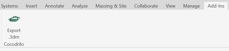
Run the export from Revit:
- Select File Name
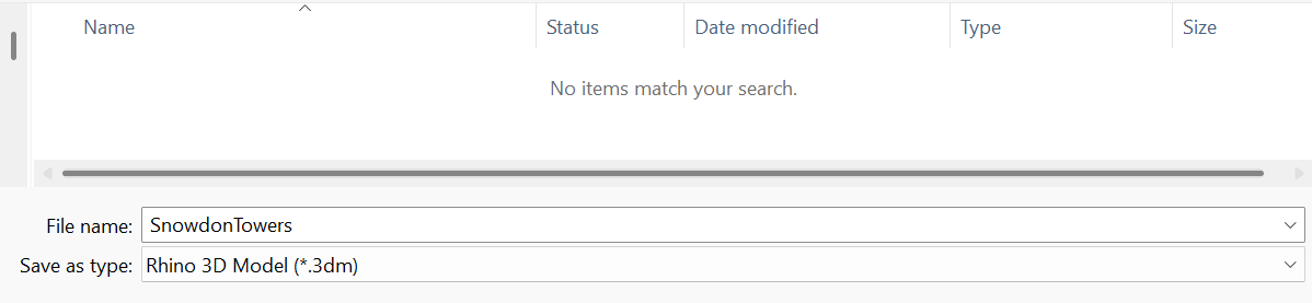
- Select your export options. Make sure to select all the parts of the model you require. Exports can sometimes be large. Unselecting metadata or the solid model reduces the file size drastically.
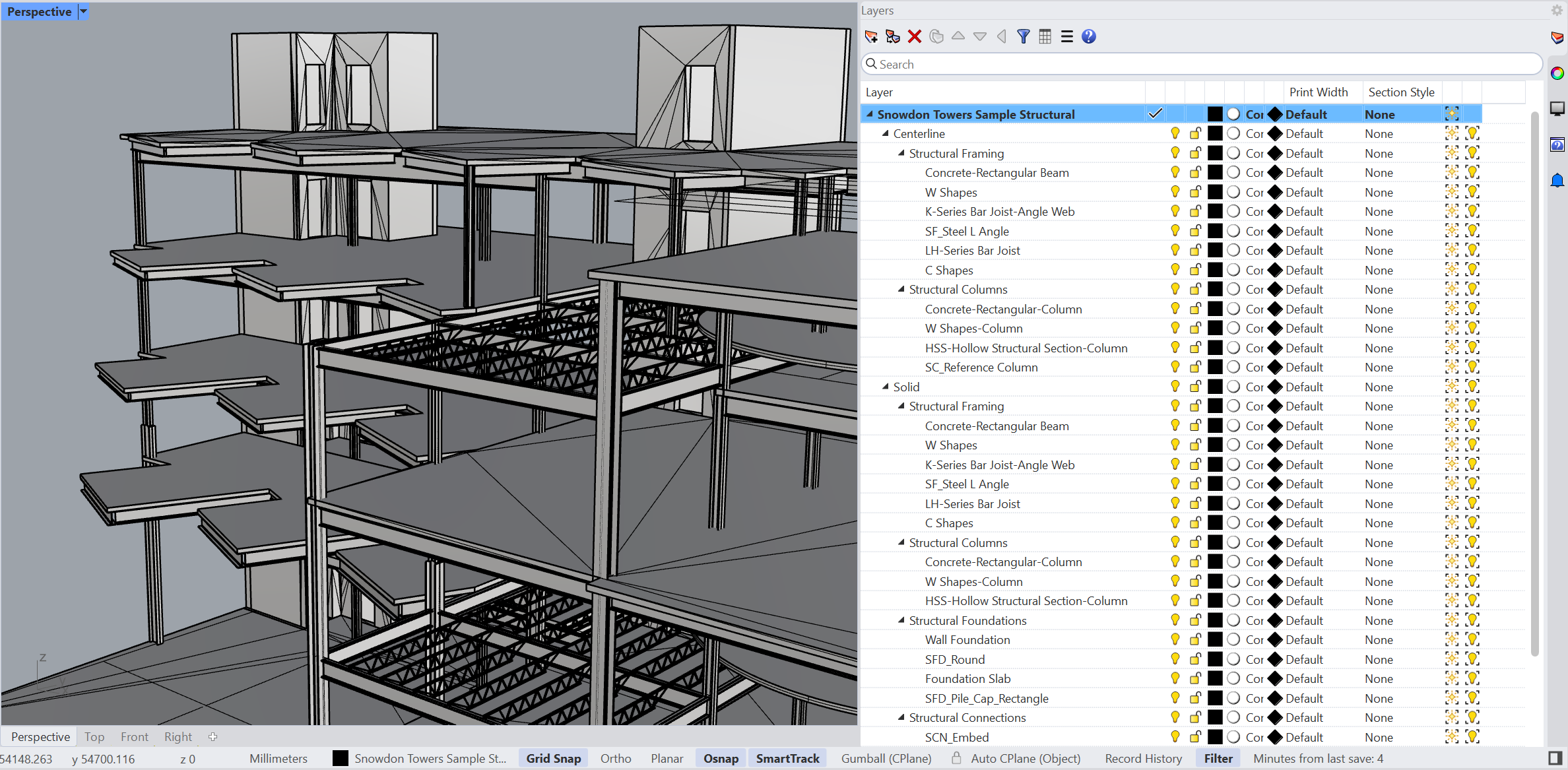
- Finally, your Rhino file should look something like this.

This workflow uses a simple tool as its starting point. However, not all models are suited to this export setup. This is where Rhino.Inside.Revit (RiR) adds value: it brings the Revit model across into Rhino and Grasshopper in a scripted environment. The great advantage of RiR is that it can easily be adapted to highly varying inputs as Revit models change. It is best to create a script that always bakes your model in the hierarchy you are comfortable working with. My recommended output of the RiR script is a Rhino file, which stores all attributes as object attributes, while carrying the categories along as the corresponding layer structure. Alternative approaches can store the geometries directly within Grasshopper files. Personally, I do not prefer this option, since it can become messier and harder to debug. Also, I like to see the geometries and their object attributes. However, this is a feasible solution.
Step two: making an analysis-suitable model
This step usually takes the most time, and it is where the fewest generalized approaches exist. In some practices it has even become standard to introduce computational design blockers: deliberate disturbances in the geometry that prevent a direct transfer between BIM and analysis. This has commercial reasons, but it also prevents blind conversions with unintended outcomes.
Some of the most common problems are misalignments, missing dependencies at certain levels, truss structures not meeting at shared points, and more. Cocodrilo introduces a variety of tools capable of merging geometries at levels, frames at points, and more, to retain consistency. Most of these tools could be built from standard Grasshopper components. However, Cocodrilo's components contain filtering algorithms in the background that allow much more efficient handling of these problems and can therefore process entire models at once. A more comprehensive guideline is coming, but in brief the most important tools offer the following functionalities:
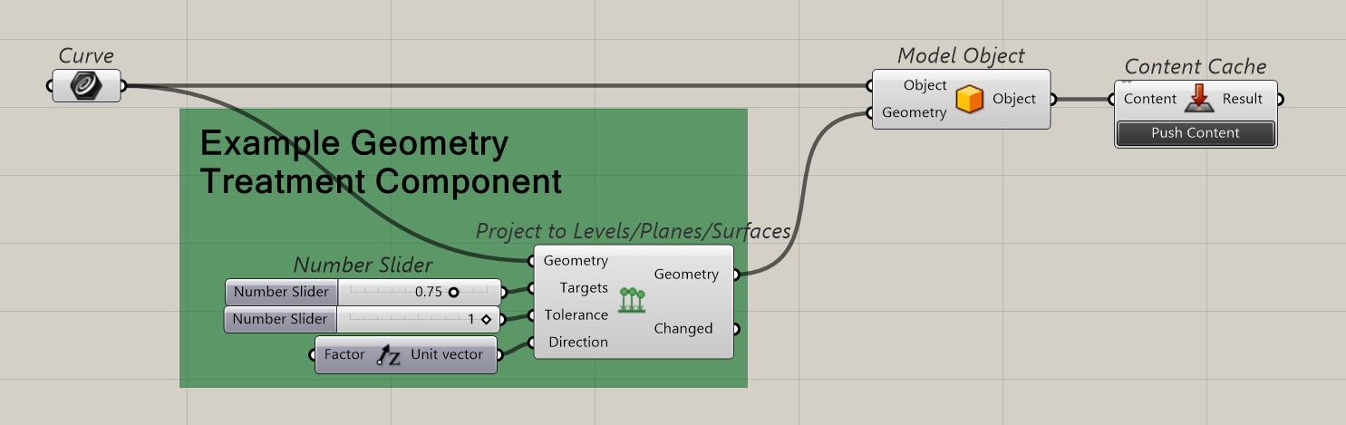
- Project onto targets (levels, planes, surfaces). This tool is very useful for matching all lines and surfaces onto levels, such as the story levels.

- Project to points (to merge at common points). This helps to node models quickly. It can sometimes be inaccurate - it all depends on whether averaging the points is the best approach.
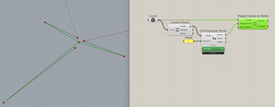
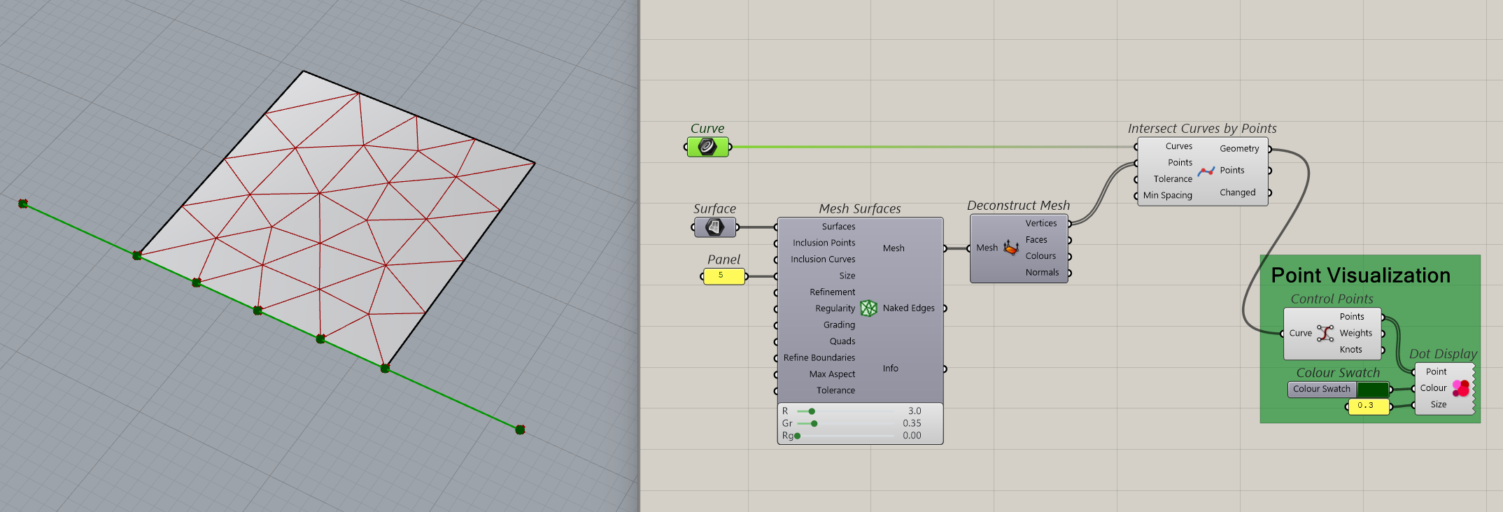
- Intersect at various targets (curve to curves / curves to levels, planes, surfaces / curves to points). Curves to points is particularly interesting once you have a composite slab and want to intersect the edging curves. Some FEM tools intersect automatically, while others rely on accurate input.
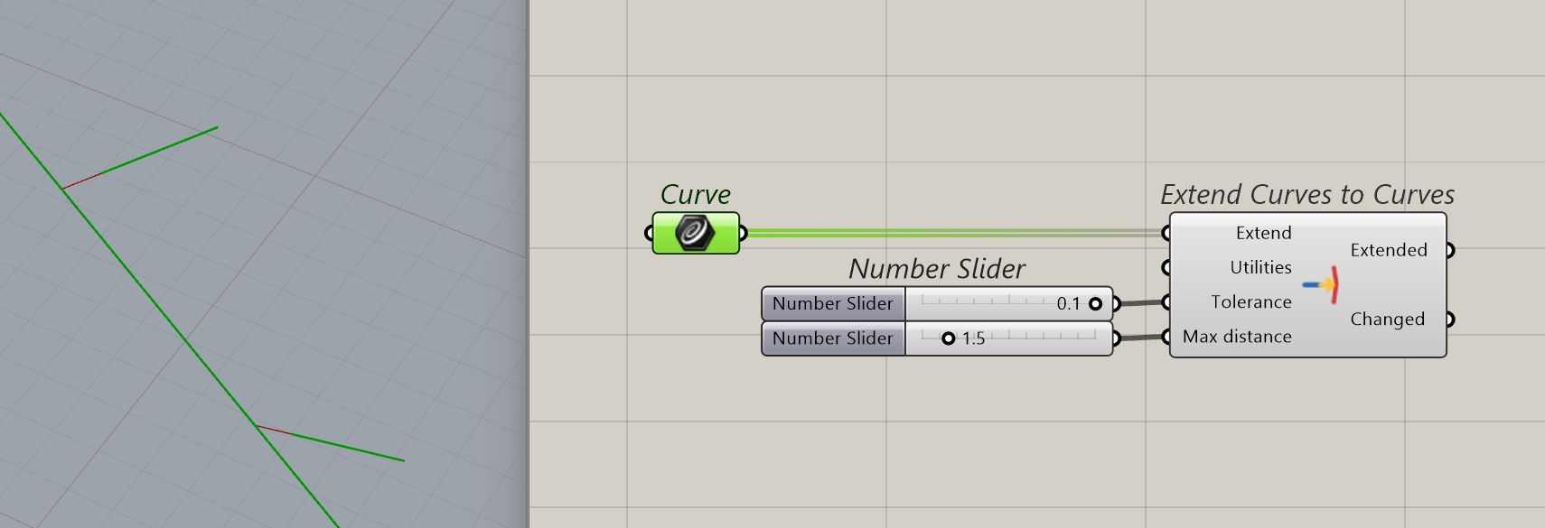
- Extend curves to targets (either other curves, or surfaces). This is often needed where superstructure beams connect with substructure beams.
A further functionality that is often required, depending on the level of exchange you are aiming for in this step, is meshing. Grasshopper already contains a large number of meshers, and plugins like Pufferfish largely cover working with meshes. Many packages also deliver their own tools that can be used independently, for example Karamba3D and Oasys GSA. The mesher that comes with Cocodrilo has been specifically optimized for use on structural analysis problems.
Once done, everything can stay in the script. However, often it is beneficial to bake these updates back to the Rhino model. The following script uses native Grasshopper components to achieve that update, while retaining the layer structure and, in particular, the required object attributes.
Step three: from Rhino model to structural model
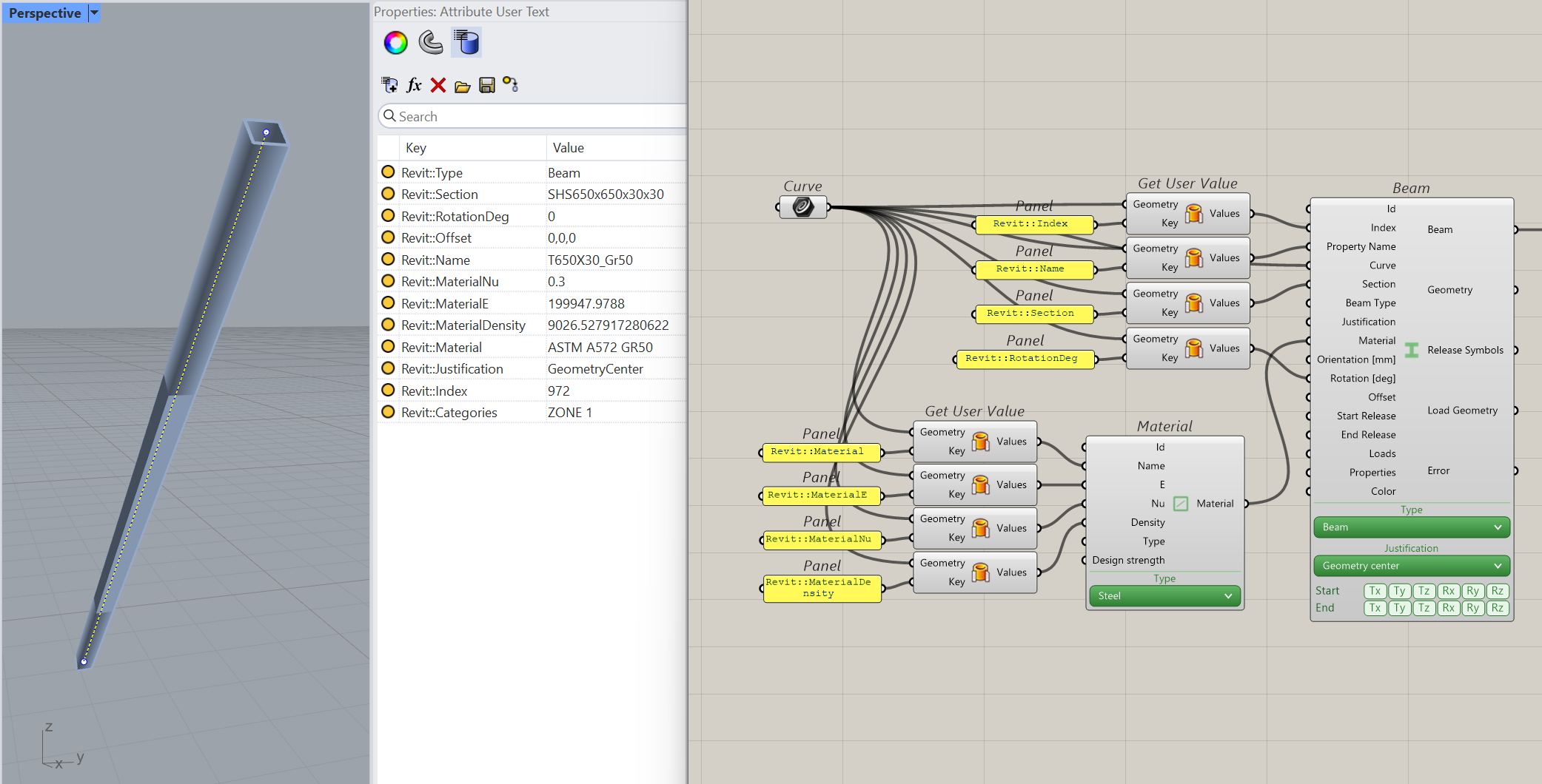
The translation is the critical step, and it is where the core of Cocodrilo sits. Physical members become proper analytical objects: surfaces become shell element carriers with their cross sections and materials carried over from the BIM data; lines and curves become beam and cable members. Supports and load cases are then attached as properties of the structural model itself.
This information can be transferred as a direct read from the object attributes. Alternatively, additional parameters may be introduced at this stage, which is the more common scenario. This is highly model- and project-dependent. This stage can often also be used to translate naming schemes, since the Cocodrilo components may interpret certain definitions differently. Because the name and the section string are independent, this information can be carried through to all stages.
Step four: analysis, in the solver you want
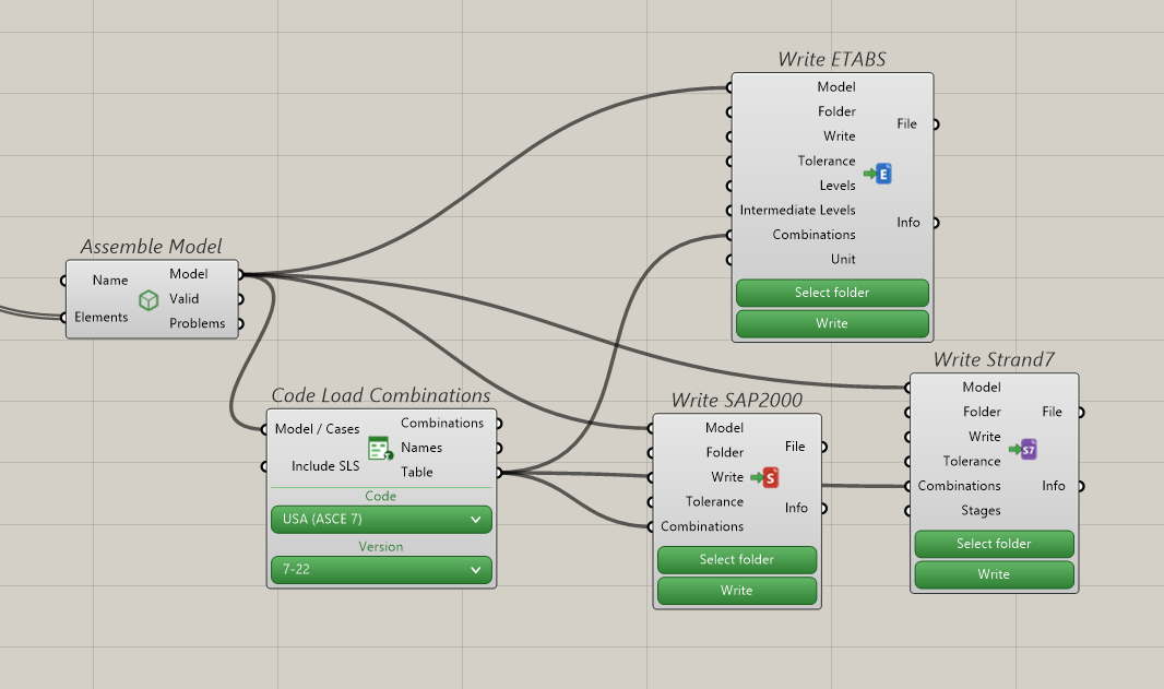
Ultimately, you can use that model for various purposes. It can be exported directly to ETABS, SAP2000, or Strand7, and more will come soon.
The newest part: talking to your model
The most recent addition is the one I would have found hardest to imagine some years ago: an AI assistant that sits directly on the structural model. Because the model is a complete, structured object, the assistant can genuinely work with it. You can ask which members carry the highest utilization, request modifications, compare two design options, or drop in an image or a sketch with a comment and have it act on that. And because it operates on the structural model, you can use all of this with very little Grasshopper knowledge.
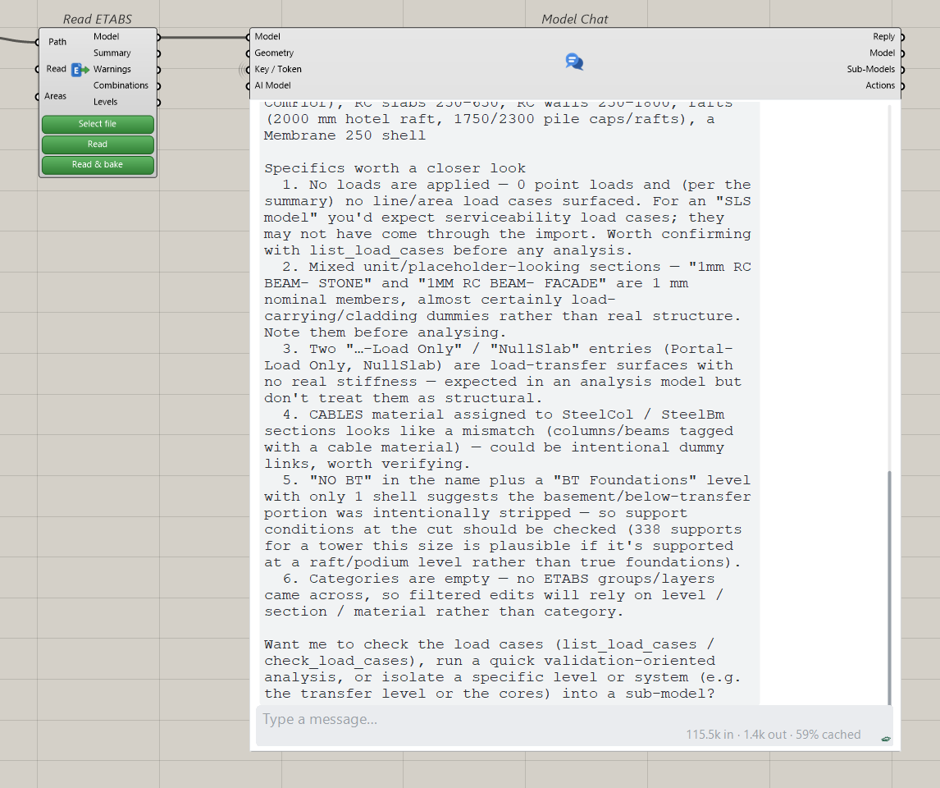
It is not AI doing structural engineering. The engineering, the verification and the responsibility stay with you. It is AI removing the mechanical work between you and your model, which in my experience is where most of the hours disappear.
Try it on your own project
This workflow is continuously evolving with every new tool that enters the market. Stay up to date with the latest developments and challenge me with your own improvements. I am not claiming that the presented workflow is the most efficient possible way. But it is one way, and I hope that in the future we will find even better ways to improve this exchange.
Comments
Tried this workflow, or stuck somewhere along the way? Leave a note below - pictures of your own setup are welcome.
No comments yet - be the first.